Patnow Power plant
At the heart of central Poland, the Patnow power station, with a capacity of 2,457 MW and contributing 10% to the nation’s electricity output, has embraced significant environmental upgrades. To align with Polish and European regulations, four lignite-fired units at the Patnow station are equipped with Flue Gas Desulfurization (FGD) plants.
After economic assessments, Patnow Power Station commissioned Rafako, a prominent Polish EPC contractor, to construct two wet limestone FGD plants, capable of handling two units each. Opting against reheating the desulfurized flue gas, the station determined that the existing chimneys were unsuitable for wet stack operations, necessitating the construction of new chimneys.
The benefits of a wet stack over a re-heat:
- Reduced pressure loss
- Higher cleaning efficiency
- Lower investment cost
- Reduced auxiliary power requirements
Innovative Approach to Chimney Construction
Collaborating with Karrena, a specialized chimney constructor, Rafako explored various designs and decided on two separate Pennguard lined concrete chimneys, each with an 8.4 m diameter. This design was found to be the most effective for the Patnow site. The innovative design allowed for the direct application of the Pennguard lining to the concrete windshield, reducing overall expenses by eliminating the need for separate flues and minimizing costly ductwork.
Efficient and Rapid Construction
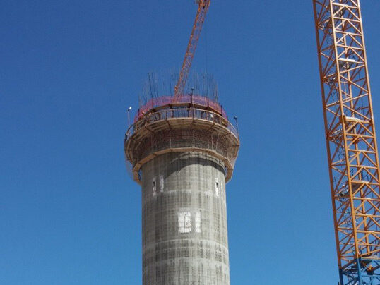
The construction of the 149 m high chimneys utilized slipforming technology, completed within just 38 days for each chimney.
Step 1 Surface preparation
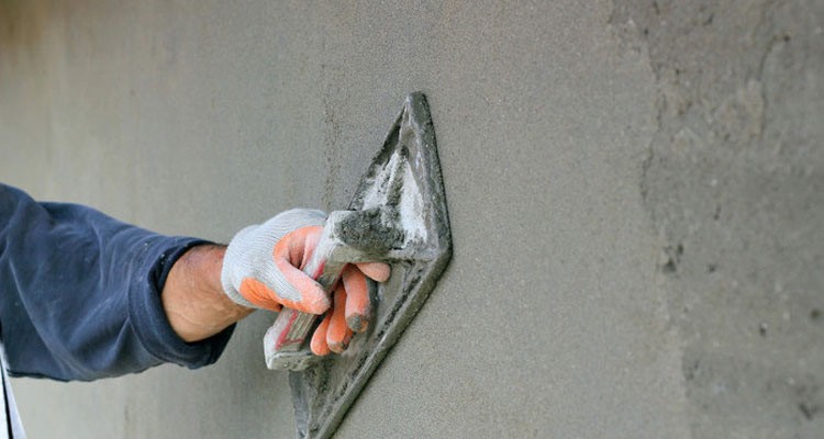
As the slipform ascends, two skilled plasterers smooth the fresh concrete inside the chimney shell, ensuring a seamless finish.
Step 2 Primer Application
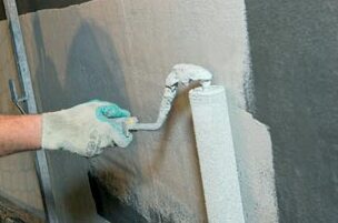
Directly after smoothing the concrete, a specialized epoxy primer is applied. This primer helps slow down water evaporation during the concrete’s curing process and provides an effective bonding surface for the Pennguard lining.
Step 3 Lining Installation
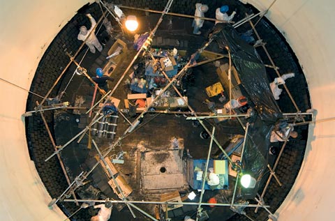
Once the chimney shell is complete, the Pennguard Block Lining System is installed. This lining, 54 mm thick, is affixed directly to the primer-coated concrete, starting from the flue gas inlet level and extending to the top.
Step 4 Floor and Finishes
After the main installation of the Pennguard lining, a false floor is installed just below the flue gas entry level in the chimney. This floor is subsequently protected with Pennguard lining. Additionally during this phase the liquid collection system is installed and checked.
The installation of the Pennguard lining is carried out by a team of 8 bricklayers. They work from a movable platform equipped with a full floor and a fast man lift, which facilitates the safe and efficient transport of both personnel and materials. Adequate lighting in the work area is crucial for safety and quality workmanship.
Economic and Spatial Advantages
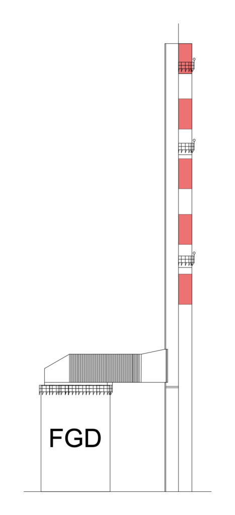
The decision to build two separate chimneys instead of one larger twin flue structure resulted in significant benefits:
- Space Efficiency: The slim chimneys required less physical space and shorter FGD outlet ducts, reducing site congestion.
- Time Savings: The rapid construction of each chimney facilitated quicker completion of the FGD project.
- Cost Reduction: The dual chimney design proved to be more economical, using less concrete and reducing the need for internal steel flues. This approach not only lowered the CAPEX but also decreased the associated ductwork by approximately 50 meters.
Overall, the Integrated Chimney Design at Patnow Power Station demonstrates an innovative approach to industrial infrastructure, yielding cost, time, and space savings while improving the plant’s environmental performance.
By now over 20 chimneys worldwide have followed this concept. Pennguard directly to the concrete windshield has now been used for more then 25 years.
